PID, short for **Potential Induced Degradation**, refers to a phenomenon where the performance of solar cells deteriorates continuously due to ion migration triggered by the potential difference between internal materials of PV modules unde
PID Effect-"Invisible Efficiency Killer" of PV Modules
I. Basic Definition and Classification
1. Core Concept
PID, short for **Potential Induced Degradation**, refers to a phenomenon where the performance of solar cells deteriorates continuously due to ion migration triggered by the potential difference between internal materials of PV modules under long-term high-voltage bias. First systematically proposed by SunPower in 2005, it is a core issue affecting the long-term reliability of PV modules.
2. Main Types (Classified by Degradation Mechanism)
| Type | Abbreviation | Core Characteristics | Impact Level | Reversibility |
|---|---|---|---|---|
| Power Attenuation Type | PID-P | The most common type; sodium ion migration damages anti-reflection coatings and pn junctions, reducing parallel resistance | Severe (power loss up to 30%) | Partially reversible |
| Short-Circuit Current Attenuation Type | PID-S | Degradation of the passivation layer on the cell surface, increasing carrier recombination | Moderate | Reversible |
| Open-Circuit Voltage Attenuation Type | PID-V | Mainly affects n-type cells, reducing minority carrier lifetime | Mild | Reversible |

II. Core Mechanism: Ion Migration is the Key
The essence of the PID effect is **electric field-driven ion migration and leakage current formation**, with the complete process as follows:
Establishment of Potential Difference:After the module frame is grounded, a high voltage difference (usually 1000-1500V systems) is formed between solar cells and the frame.
Formation of Conductive Channels:- Moisture absorption by encapsulation materials (e.g., EVA) in high-humidity environments (or condensation) forms a conductive medium required for ion migration.
Ion Migration:Under negative bias, mobile ions such as **sodium ions (Na⁺)** in glass and encapsulation materials migrate toward the cell surface.
Performance Degradation:Sodium ions accumulate on the surface of the cell's anti-reflection layer (SiNₓ), damaging the passivation effect and resulting in:
- Decreased parallel resistance and increased leakage current
- Reduction in fill factor (FF), open-circuit voltage (Voc), and short-circuit current (Isc)
- Ultimately, significant attenuation of the module's maximum power (Pmax)
III. Key Influencing Factors (Three Essential Conditions for Occurrence)
Voltage Conditions(Necessary Condition):The higher the negative bias voltage of the module relative to the ground, the more significant the PID effect; generally, the more modules in series (higher system voltage), the greater the risk.
**Environmental Conditions(Accelerating Condition):
- Humidity: Ion migration rate increases sharply when relative humidity exceeds 60%
- Temperature: The PID rate approximately doubles for every 10°C increase; attenuation is fastest at 85°C
Module-Specific Factors:
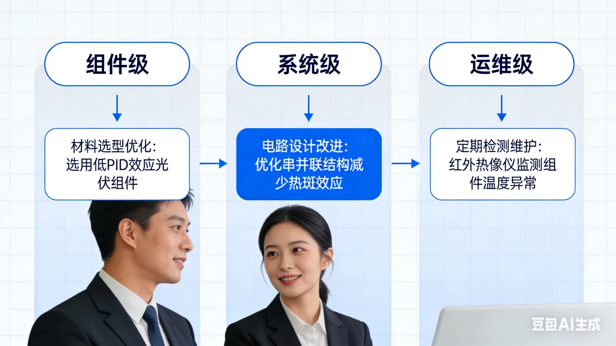
- Encapsulation Materials: Early EVA is prone to moisture absorption with poor PID resistance; POE materials perform better
- Glass Type: Ordinary soda-lime glass contains a large amount of sodium ions; low-sodium glass can reduce risks
- Cell Type: p-type cells are more sensitive to PID, while n-type cells (e.g., TOPCon, HJT) have stronger PID resistance
- Encapsulation Process: Lamination quality and edge sealing directly affect moisture intrusion
IV. Hazards and Impacts
- Power Generation Loss**: 10%-30% module power attenuation directly impacts the power plant's IRR (Internal Rate of Return)
- Service Life Reduction: Long-term PID effect may cause irreversible damage such as hot spots and microcracks in modules
- Increased Operation and Maintenance Costs: Additional resources need to be invested in testing, repair, and even module replacement
- Safety Risks: Increased leakage current may cause local overheating of modules, posing fire hazards
V. Testing Methods and Standards
1. Laboratory Testing (Factory Verification)
IEC TS 62804-1 标准: Specifies three testing methods to evaluate the PID resistance of modules
- Dark-State Testing: Apply negative bias voltage (typically -1000V) to modules and maintain them in an 85℃/85%RH environment for 96 hours
- Light-State Testing: Simulate actual operating conditions to evaluate PID effect under illumination
Power Attenuation Criterion: A Pmax attenuation rate ≤ 5% before and after testing is considered qualified, and ≤ 2% is excellent
2. On-Site Testing (Power Plant Operation and Maintenance)
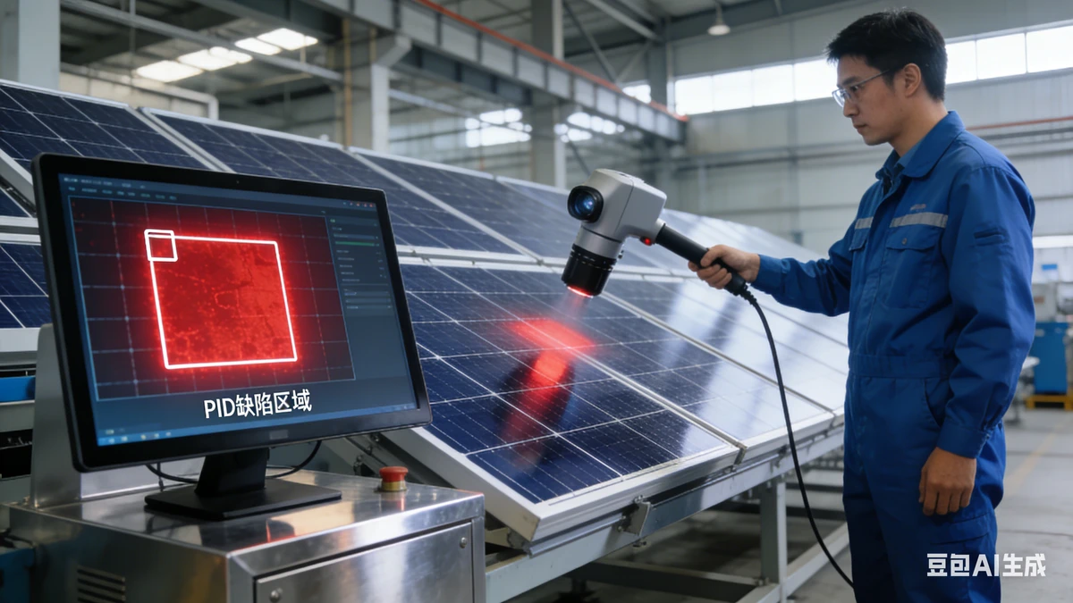
- EL (Electroluminescence) Testing: EL images of PID-affected modules showblack spots/streaks,corresponding to leakage current areas
- IV Curve Testing: Compare the actual Pmax of modules with the nominal value to calculate the attenuation rate
- Leakage Current Monitoring: Install leakage current sensors to real-time monitor the leakage current of modules to the ground (normal value < 10μA)
- Thermal Imaging Testing: Severe PID areas generate local overheating due to leakage current, which can be detected as abnormal hot spots via thermal imaging